Comprehensive Metal Building Terminology and Definitions: Your Ultimate Steel Construction Glossary
Metal building terminology collects the essential vocabulary designers, contractors, owners, and project managers use to specify, build, and maintain steel structures. This glossary explains core components, envelope systems, foundation and site terms, applicable loads and standards, and concise answers to common questions so stakeholders can read plans, attend site meetings, and communicate with suppliers with confidence. Readers will learn clear definitions, how components function together, selection considerations, and which standards govern design and safety; the guide emphasizes practical application and snippet-ready answers for rapid reference. Many project stakeholders travel frequently between showrooms, job sites, and supplier meetings, so for convenient professional transportation to site visits or supplier meetings, consider booking limousines with Metal Building Contractors Near Me. The article is organized into sections: core structural components, envelope functions, foundation and site terminology, industry standards and loads, and a focused Q&A to resolve common term confusion, each designed to support decision-making on pre-engineered metal building projects.
What Are the Core Components of Metal Buildings?
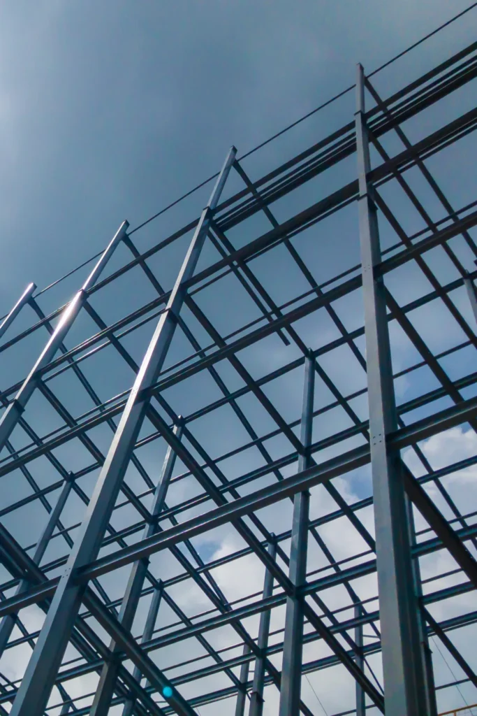
Core components of a metal building include primary framing (columns, rafters, beams) and secondary framing (purlins, girts, bracing) that work together to form load paths and support cladding. Primary framing transfers major gravity and lateral loads to foundations, while secondary members carry cladding and distribute localized loads to the primary frames. Understanding both categories clarifies how roof, wall, and foundation systems interact and why material choices (rolled vs cold-formed steel) and connection details matter for performance and durability.
The following comparison table summarizes common components, their typical materials, and principal functions to support quick specification choices and procurement discussions.
Primary structural components overview and comparative functions:
| Component | Typical Material | Primary Function |
|---|---|---|
| Column | Rolled steel / Cold-formed steel | Vertical load transfer to foundation; supports rafters/beams |
| Rafter (Ridge/Beam) | Rolled or fabricated steel | Spans between columns; supports roof loads and decking |
| Beam | Rolled steel / Welded shapes | Carries bending loads and distributes loads to columns |
This table helps teams quickly compare materials and roles when reviewing shop drawings, which leads naturally to detailing primary framing connections and load paths in project specifications.
Understanding Primary Structural Elements: Columns, Rafters, and Beams
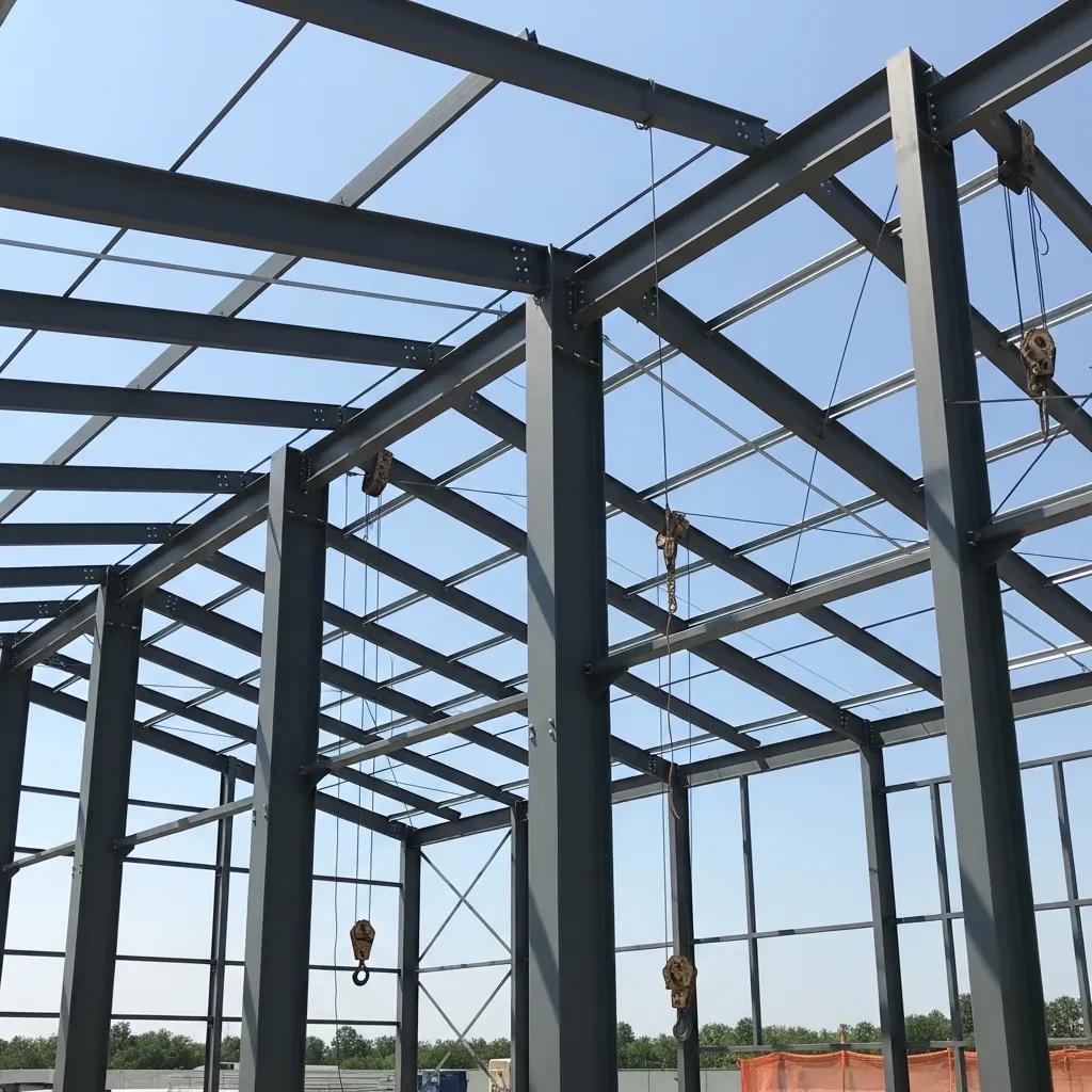
Columns, rafters, and beams form the primary load-bearing skeleton of a metal building, each defined by its role in the vertical and lateral load path. Columns are vertical members designed to carry axial loads and bending, often specified as rolled shapes or tapered welded sections; rafters (sometimes integral with beams in rigid frames) span between columns and carry roof loads to beams or columns. Beams bridge between columns or support secondary members and are detailed for bending, shear, and deflection criteria; connection design is critical because it establishes how loads transfer and where bracing must be applied. Typical specifications will note material grade, section type, connection plate sizes, and tolerances, and practitioners should inspect how primary members tie into base plates and anchor bolts to ensure proper load transfer to the foundation. Properly understanding these primary elements sets the stage for selecting compatible secondary framing that supports cladding and service loads.
Exploring Secondary Framing: Purlins, Girts, and Bracing
Secondary framing — purlins, girts, and bracing — supports roof and wall panels and conveys their loads to the primary frames, with profiles chosen for span, load, and attachment method. Purlins are horizontal roof supports (common profiles include Z-purlin and C-purlin) that sit atop rafters or eave struts and support roof panels; girts do the same for walls, spacing and sizing based on panel type and wind loads. Bracing systems (X-bracing, cable bracing, or rigid diaphragms) stabilize frames against lateral loads and prevent excessive sway; specification should include bracing expected deflection limits and connection anchorage. Considerations for spacing, fastener type, and thermal movement are crucial when specifying secondary framing because incorrect choices can lead to panel failure or accelerated fatigue; these considerations naturally lead into panel selection and envelope detailing, discussed next.
The intricate design of cold-formed steel purlins, with their flexible cross-sectional shapes and complex governing rules, presents a significant challenge for optimization, often requiring advanced computational methods.
Optimizing Cold-Formed Steel Purlin Design
An important advantage of cold-formed steel is the great flexibility of cross-sectional shapes and sizes available to the structural steel designer. However, the lack of standard optimized shapes makes the selection of the most economical shape very difficult. This task is further complicated by the complex and highly nonlinear nature of the rules that govern their designs. In this thesis, genetic algorithms are used to carry out the optimization of cold-formed steel purlins, which are assumed to be continuous over two spans subjected to a gravity load.
Optimum design of cold-formed steel purlins using genetic algorithms, W Lu, 2003
How Do Metal Building Envelope Components Function?
The building envelope — roof panels, wall panels, flashing, ridge caps, and soffits — provides weather protection, thermal control, and the visible finish of a metal building while interacting with structural framing to resist loads. Envelope components are chosen for profile, material, coating, and fastening approach to meet thermal, acoustic, and water-shedding requirements, with insulation and vapor control integrated to manage condensation and energy performance. Proper detailing at penetrations, eaves, and ridges prevents water intrusion; designers must coordinate panel profile with purlin or girt spacing and specify compatible fasteners and sealants.
The following table compares common roof and wall panel types, their profiles, materials, and frequent applications to guide specification and procurement conversations.
Overview of common panel attributes and uses:
| Panel Type | Typical Profile | Common Materials / Coatings |
|---|---|---|
| R-Panel | Ribs with exposed fasteners | Galvanized steel, painted coatings |
| Standing Seam | Concealed fasteners, interlocking seams | Galvalume, stainless steel, PVDF coatings |
| Corrugated | Scalloped profile | Galvanized steel, aluminum |
This comparison helps teams match panel performance to project priorities such as cost, longevity, and aesthetic requirements before finalizing fastener and insulation systems.
Roles of Roof and Wall Panels in Metal Construction
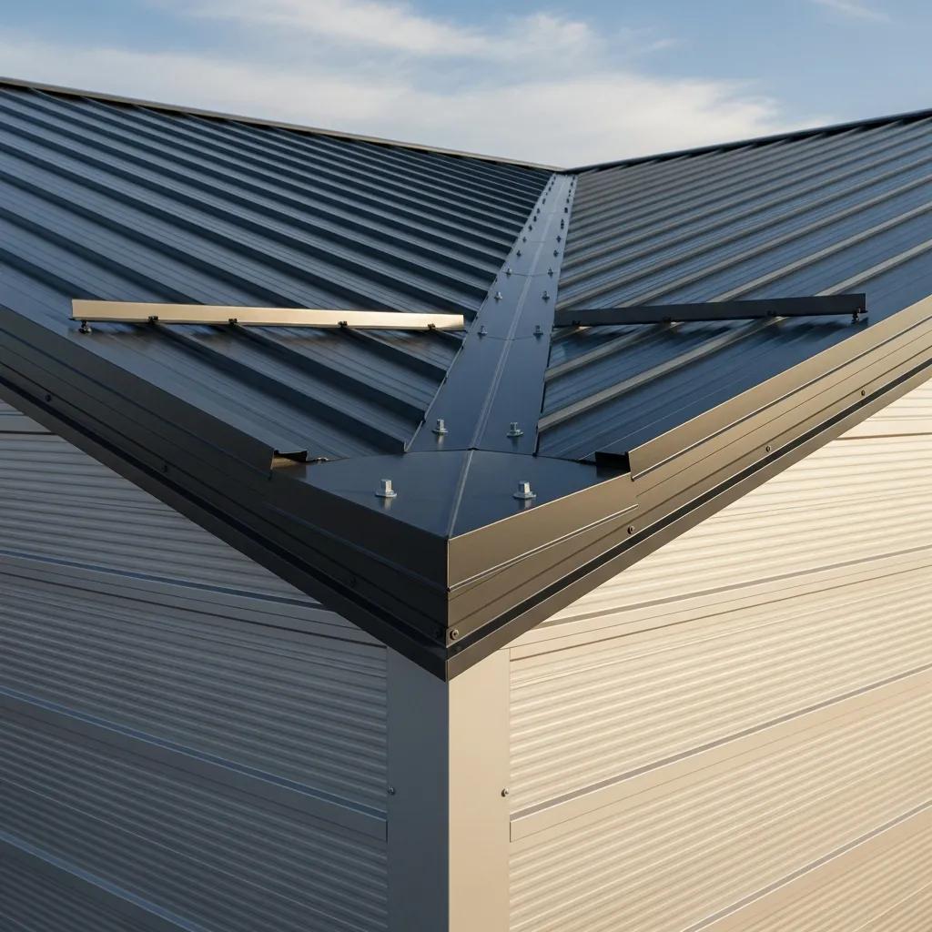
Roof and wall panels act as the primary weather barrier and a portion of the building’s thermal envelope, with profile and material selection affecting drainage, load capacity, and attachment details. Panels designed for water shedding (corrugated and R-panel) rely on slope and lap details, while standing seam systems provide improved leak resistance through concealed-fastener profiles suited for low-slope roofs. Material choice—galvanized steel, galvalume, or aluminum—affects corrosion resistance and maintenance cycles; coatings such as PVDF improve color retention and durability. Fastening methods (exposed screws versus concealed clips) influence thermal movement detailing and potential leak paths, so alignment between panel type and substructure (purlin spacing, eave conditions) must be coordinated during design and erection. These panel roles point directly to accessory detailing, including flashing and ridge elements, which ensure durable transitions.
Importance of Flashing, Ridge Caps, and Soffits
Flashing, ridge caps, and soffits are accessory components that seal transitions, ventilate roof cavities, and finish eave and ridge junctions to prevent moisture ingress and pest entry. Flashing directs water away from joints at openings, roof-wall intersections, and penetrations; it is typically fabricated from the same or compatible coated metals and requires careful overlap and sealant selection. Ridge caps cap the roof ridge to shed water while often integrating ventilation for attic or cavity spaces, and soffits close eave openings while permitting intake ventilation when designed as part of a balanced ventilation system. Common failure points include improperly lapped flashing, missing sealant at fasteners, and misaligned ridge vents; specifying installation tolerances and inspection checkpoints reduces long-term leakage risk. Correct accessory detailing completes the envelope and informs foundation protection and moisture control strategies covered next.
What Are the Key Foundation and Site Terms in Metal Building Construction?
Foundation and site-preparation terms crucial to metal buildings include anchor bolts, base plates, slab and footing types, soil bearing capacity, and site drainage measures that ensure structural stability and longevity. Foundations must accommodate concentrated loads from primary frames and resist uplift and lateral forces transmitted through anchor systems; choice among slab-on-grade, strip footings, or piers depends on soil conditions, load demands, and budget. Site preparation—compaction, subgrade treatment, and perimeter drainage—controls settlement risk and protects foundations from seasonal moisture fluctuations; coordinating geotechnical recommendations with foundation design avoids costly retrofit work.
The table below compares typical foundation types for metal buildings, outlining use-cases, advantages, and limitations to support decision-making during early project phases.
Foundation type comparison for metal buildings:
| Foundation Type | Typical Use | Pros / Cons |
|---|---|---|
| Slab-on-grade | Warehouses, light industrial | Cost-effective, provides floor surface; less suitable on expansive soils without treatment |
| Strip footing | Continuous support under walls | Economical for moderate loads; requires good subgrade |
| Pier / Pile | Poor soils or deep foundations | Suitable for weak soils and heavy point loads; higher cost and complexity |
This comparison guides selection and leads into anchor detailing and inspection best practices that ensure secure connections between structure and foundation.
Anchor Bolts and Base Plates: Securing the Structure
Anchor bolts and base plates secure columns to foundations and are the final link in the structural load path, resisting uplift, shear, and moment forces according to connection design and anchor embedment. Anchor bolt types include cast-in-place threaded rods and post-installed anchors; embedment depth, bolt pattern, and grout under base plates are specified to meet design tensions and tolerances. Base plates distribute column loads to concrete and often include shims and grout to achieve proper alignment; inspection should verify bolt location, verticality, and proper grout fill before load application. A contractor checklist for anchors includes verifying bolt layout to shop drawings, ensuring correct nut rotation and torque where specified, and documenting grout cures, which directly affects foundation choice and site preparation recommendations discussed next.
Foundation Types and Their Roles in Steel Buildings
Choosing among slab-on-grade, strip footings, and pile/pier foundations depends on soil bearing capacity, building loads, and site constraints, with each option balancing cost and performance differently. Slab-on-grade provides an integrated floor and foundation for uniform loads; it is cost-effective on stable, well-draining soils but may require moisture barriers and insulation for energy control. Strip footings support continuous walls and are economical for moderate loads but need controlled subgrade preparation to avoid differential settlement. Pile or pier foundations transfer loads to deeper, competent strata where near-surface soils are weak, trading higher installation costs for predictable performance on challenging sites. Summarizing selection criteria helps teams align geotechnical reports with structural plans and coordinate logistics—such as safe, reliable transportation for site inspections—which can be supported by professional limousine services for stakeholder visits.
- For project site visits and team coordination, consider arranging professional transportation when multiple stakeholders attend inspections to keep schedules efficient and equipment secure.
- Metal Building Contractors Near Me offers limousine booking for convenient travel to supplier showrooms and jobsite meetings, which can ease logistics for teams managing complex foundation reviews.
- Using coordinated transport reduces downtime between site walkthroughs and vendor meetings, helping owners and managers stay focused on technical decisions rather than travel details.
These practical logistics notes link foundation selection and inspection planning to on-the-ground coordination needs that follow during construction.
Which Industry Standards and Loads Govern Metal Building Design?
Metal building design is governed by building codes and loading standards that define dead, live, wind, and seismic loads, while professional organizations publish manuals and design guides that clarify practical application of these requirements. Dead loads are permanent weights from structure and fixed equipment; live loads are transient occupancies and maintenance loads; wind and seismic loads are lateral forces specified by code with site-specific parameters. Design references such as the International Building Code and ASCE standards provide calculation procedures, load combinations, and safety factors; industry organizations publish complementary guidance specific to steel construction and pre-engineered systems. The next paragraph lists concise definitions and practical implications of each load type to support featured-snippet style answers for designers and inspectors.
Key load definitions and design implications:
- Dead Load: Permanent structural weight that defines baseline member sizing and foundation compression.
- Live Load: Variable occupancy loads influencing floor framing and serviceability limits.
- Wind Load: Site-dependent lateral and uplift forces requiring envelope detailing and bracing design.
- Seismic Load: Dynamic ground-motion forces affecting connection ductility and lateral-force-resisting systems.
Understanding Building Codes and Load Types: Dead, Live, Wind, and Seismic
Dead, live, wind, and seismic loads are quantified by code to ensure safety under expected service and extreme conditions, with each load type affecting member sizing, connection design, and foundation requirements. Dead loads include self-weight of framing, panels, and fixed equipment and influence axial and shear demands; live loads vary by occupancy and are critical for floor systems and roof access planning. Wind loads produce uplift and lateral pressures that require roof anchorage details, eave strut selection, and cladding attachment checks; seismic design emphasizes ductility and continuity in load paths to dissipate energy. Designers apply code-specified load combinations and reduction factors to size members and choose bracing and foundation solutions, so familiarity with current code editions and site-specific parameters is essential for compliant, resilient metal building design.
Role of Organizations: AISC, MBMA, and AISI in Metal Building Standards
Professional organizations provide design manuals, specifications, and best-practice guides that complement building code requirements and often address steel-specific detailing and fabrication practices. The American Institute of Steel Construction (AISC) publishes steel design specifications and connection design guidance; the Metal Building Manufacturers Association (MBMA) offers design guides specifically for pre-engineered metal buildings, including framing and roof/wall systems; the American Iron and Steel Institute (AISI) provides standards for cold-formed steel design. Practitioners reference these publications to resolve fabrication tolerances, member selection, and detailing conventions, and they should consult the latest editions and errata for current recommendations. Knowing which organization to consult for a given design question accelerates compliance and helps teams implement efficient, code-aligned solutions.
Further elaborating on design methodologies, the concept of semi-rigid frame design, which accounts for non-linear connection behavior and utilizes the AISC LRFD approach, offers advanced considerations for structural stability and member sizing.
Semi-Rigid Frame Design Methods for Steel Structures
Design of semi-rigid (PR) frames focuses on behavior characteristics of non-linear connections, including their substantially different loading and unloading characteristics. Moment-rotation connection representations, such as the three-parameter power model, facilitate the calculation of stiffness data required for frame analysis. In this paper, the connection characteristics are described in terms of linearized connection stiffnesses that are calculated on the basis of expected connection loads. This allows for the use of first-order analysis to determine structural stability, serviceability and member load effects. The design method detailed in this paper includes the concurrent selection of connection and member sizes. The LRFD approach of AISC is utilized, including the provisions that rely on amplification factors to account the provisions that rely on amplification factors to account for second-order effects. Member section checks are made with unbraced length K-factors
Semi-rigid frame design methods for practicing engineers, 1999
What Are Common Metal Building Terminology Questions Answered?
This FAQ-style section answers common definitional questions with concise, snippet-optimized responses that help nontechnical stakeholders and new practitioners quickly understand key terms. Short, direct answers are followed by brief elaborations and internal navigation cues so readers can explore deeper technical sections as needed.
The following Q&A entries target high-use search queries and practical misunderstandings that arise during specification, tendering, and construction phases. Each brief answer is optimized for clarity and immediate usefulness, then points to related sections for fuller context.
What Is a Purlin and Its Function in Metal Buildings?
A purlin is a horizontal secondary framing member that supports roof panels and transfers roof loads to primary rafters or frames. Purlins are commonly formed as Z-purlins or C-purlins and are selected based on span, spacing, and point loads from rooftop equipment or snow; profile choice influences attachment method and thermal movement behavior. Proper purlin specification includes section properties, bracing requirements, and fastener details to prevent local buckling and to ensure compatibility with the chosen roof panel profile. For visual guidance, include elevation and section diagrams showing purlin-to-rafter connections during design reviews.
How Does a Rigid Frame Support Metal Building Structures?
A rigid frame is a moment-resisting primary frame composed of columns and rafters connected to act as a single structural unit, enabling clearspans and efficient load transfer to foundations. Rigid frames provide large unobstructed interior spaces because they resist bending via moment connections rather than truss webs, making them common in warehouses and industrial buildings requiring wide spans. Components include columns, rafters, and often haunches at connections to increase moment capacity, and design advantages include simplified erection and fewer secondary members, though fabrication tolerances and connection rigidity must be controlled.
Further emphasizing the benefits of this structural approach, research highlights the significant advantages of pre-engineered metal buildings, particularly their cost-effectiveness and ability to create expansive, column-free spaces.
Advantages of Pre-Engineered Metal Buildings
In these days, the cost and time of construction is in more priority for the client with the large working area for various uses. For the economically and minimum loss of material, pre-engineered building system (PEBs) has many advantage, because it gives more column free space at low cost. Pre-engineered metal buildings are more reliable for various uses like complex industrial facilities, warehouses and distributioncenters, stock-house, shopping malls, resort, motor court, office, cabin, service complex, aircraft-hanger, athletics and fun stadium, study places, temples, hospitals, and any types of industrial structures. In the pre-engineered metal building system, the rigid frame consists of slab, wall are connected with primary member (beam and column). This frame can spanlarge spacing without any intermediate columns.
Advantages of Pre-Engineered Building over Conventional Building, DR Singh, 2020
- Comparison List: Common decision factors when choosing rigid framesSpan requirements: Rigid frames suit large clearspans with fewer obstructions.Cost considerations: Fabrication and connection detailing affect cost-effectiveness.Serviceability: Deflection limits and vibration criteria influence frame sizing.
These decision factors help teams pick between rigid frames and alternating systems during early project planning and then coordinate fabrication drawings accordingly.